Airframe Simulation and Testing
FEA, Aviation, Sub-Frame, Factor of Safety, Non-Destructive Tests
In 2017 I was involved in an aircraft redesign project. It was a two-seat lightweight training aircraft equipped with a tubular aluminium subframe. The task scope consisted of reverse engineering, FEA, subframe revision and final testing. As a part of the flight tests, I flew over 20 hours on this prototype to validate the quality of the redesign.
Project summary
• CAD development
• Finite elements analysis (FEA)
• Conducting tests
• Critical design review and analysis
Responsibilities
1. Definition of the load cases
2. Airframe analysis
Project objectives
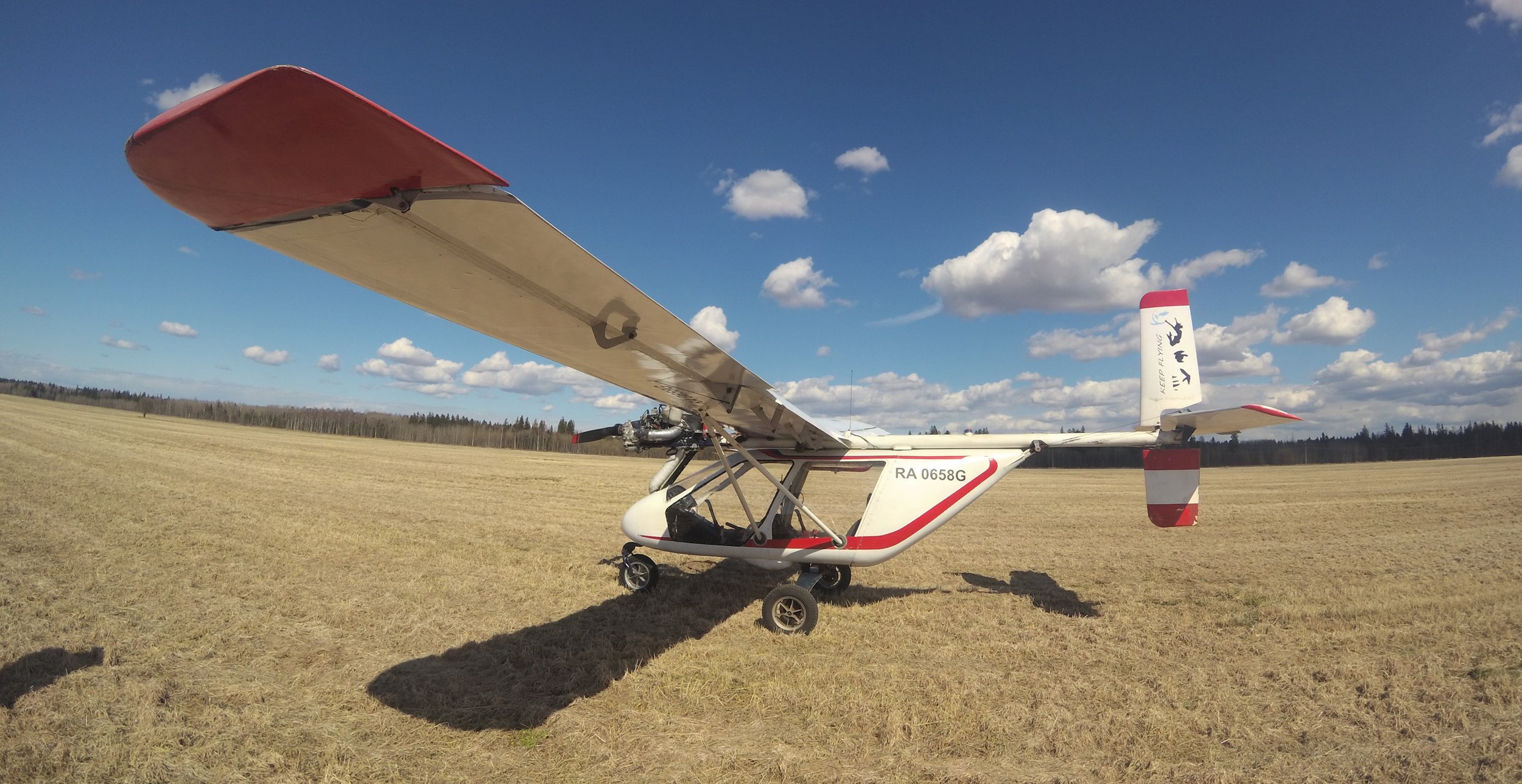
The given aeroplane was designed for observation flights (high wing position) and had a compartment for two pilots assembled around an aluminium airframe. The assembled airframe is shown in the picture below and has a total mass below 40kg, including a top engine subframe. During the extensive redesign, I decided to define the most critical loads acting on the airframe and fuselage. The redesign required a new fuselage that could contain the cabin and the stressed glass fibre tail section, so understanding the acting forces was crucial.
1. Definition of the load cases
For a clear understanding of the loads, I installed two accelerometers (one in the cabin and the second on the very edge of the tail) and analysed the following scenarios:
• Take off
• Horizontal flight in moderate turbulence
• Dive recovery initiation or high-speed pitchback (with 80-degree roll)
• Landing and touchdown
Tests revealed that the take-off and horizontal flight create as twice as less load to the tail section than a dive recovery initiation or quick pitch variation at maximum speed. A quick steep descending (negative pitch variation) creates less load due to wing profile geometry. At the same time, it has no critical effect on the airframe due to the tensile load character on the tail bracing supports.
After the tests, we decided to increase FoS according to the NASA-STD standard because of unclear load conditions, especially when operated by trainees.
According to the measured data, I focused on the following critical cases
• Dive recovery initiation < 2,1G
• Low speed emergency dive > − 0,9G
For the above-mentioned cases, I decided to implement the following factors of safety (FoS):
• 2,5 fasteners FoS (1,5 for a joint slip at limit load)
• 2,0 Ultimate FoS for collapsing members (tubes under compression)
• 2,0 Ultimate FoS on limit load (applied to ultimate tensile strength)
• 1,3 FoS on material σ(0.2%)
The FoS chosen above will guarantee structural integrity under the limit loads and provide protection in case of thickness imperfection and material properties variation. At the same time, an increased FoS shifted the member’s stress closer to the endurance limit of the material, which made the lifetime of the airframe almost unlimited.
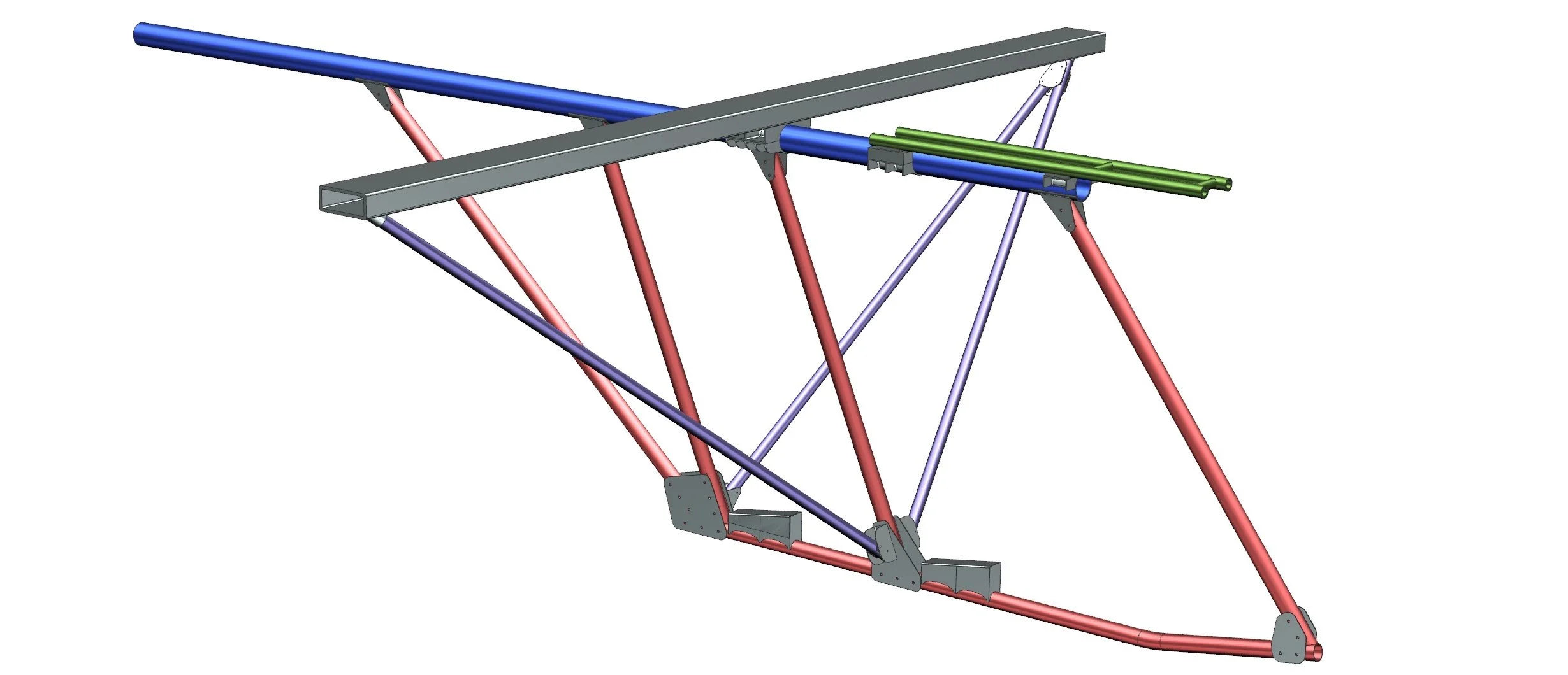
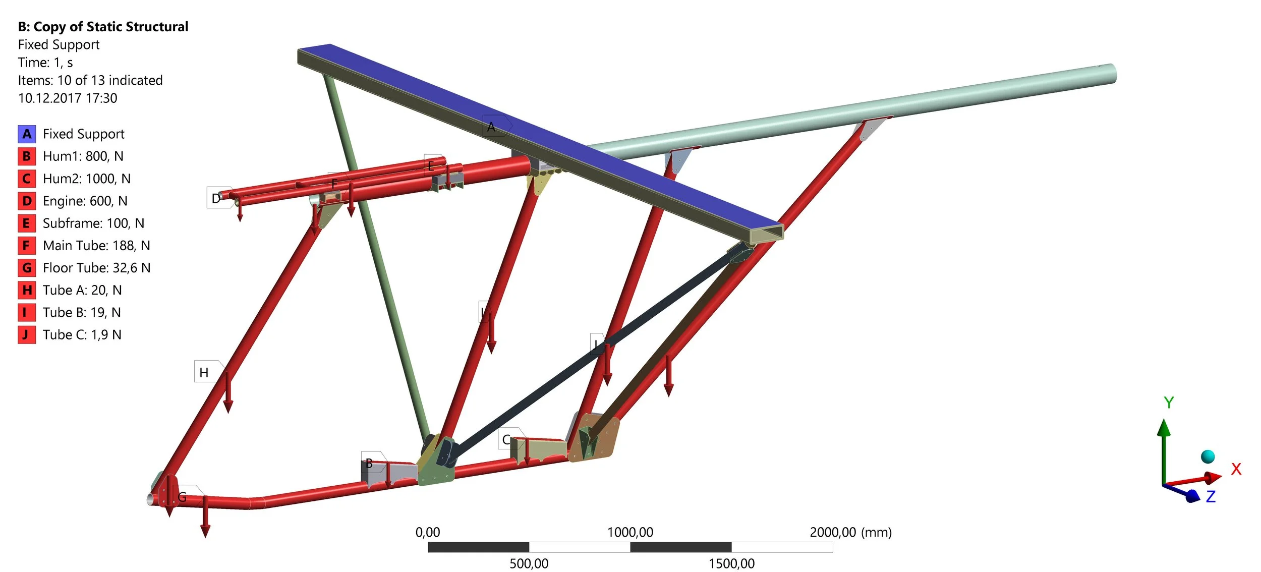
For the finite element analysis (FEA), we measured all the components' actual thickness and mass. Additionally, the disassembly and study of the flying prototype showed no sign of fatigue cracks, bent cross sections or stretched bolts. Using NX and Ansys WB Mechanical, I created a mid-surface shell model for all the airframe members. To simulate the correct stress distribution, I added the point masses representing the engine (60kg), two pilots (80kg and 100kg), and the distributed force representing the weight of the members.
2. Airframe analysis
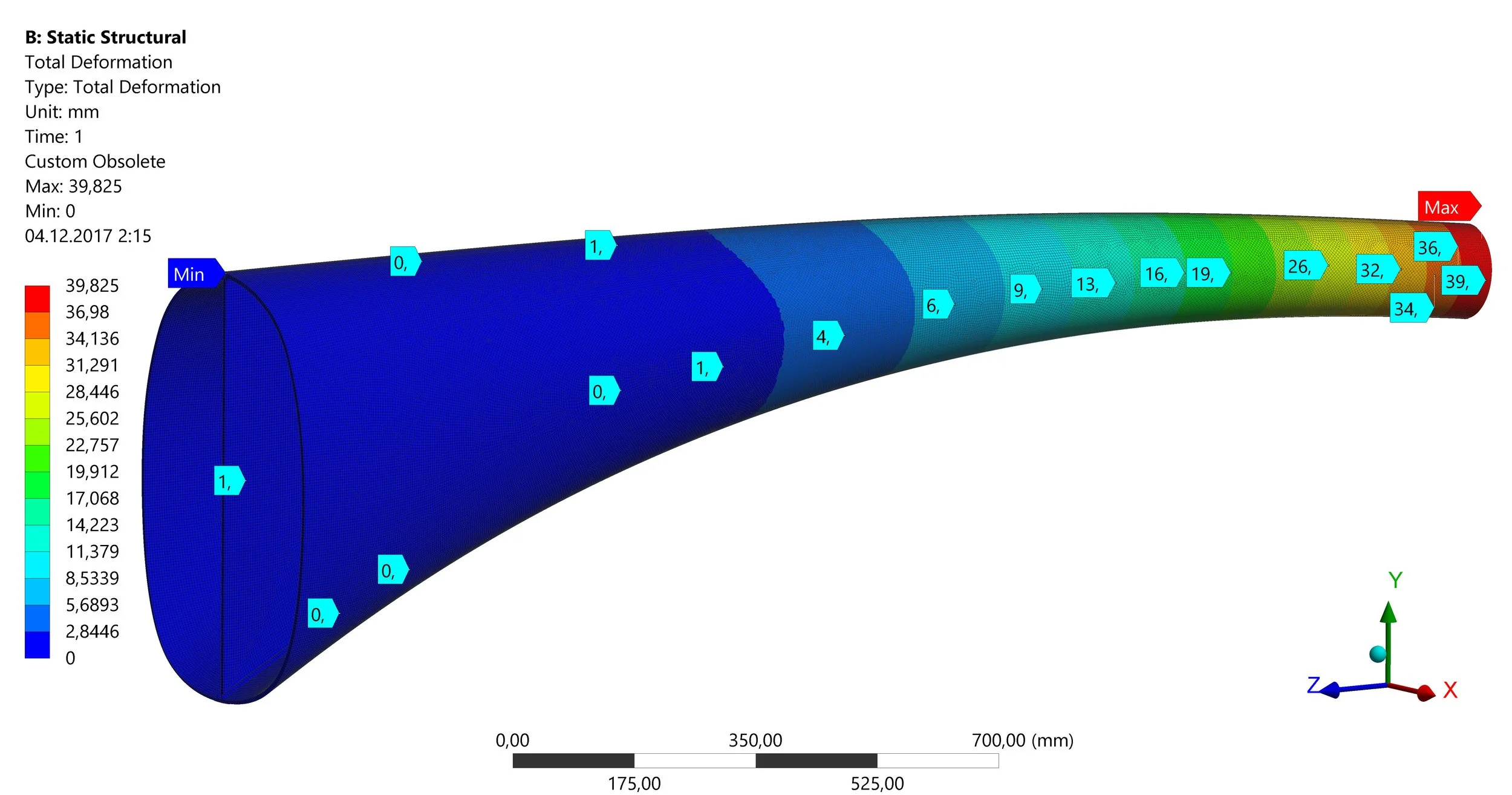
Due to the lack of optimisation simulations and a safe time margin for the project, I used a fine mesh with SHELL181 elements. The figures below show a directional deformation (Y axis pointed upward) and the FoS to σ(0.2%) stress for the dive recovery scenario.
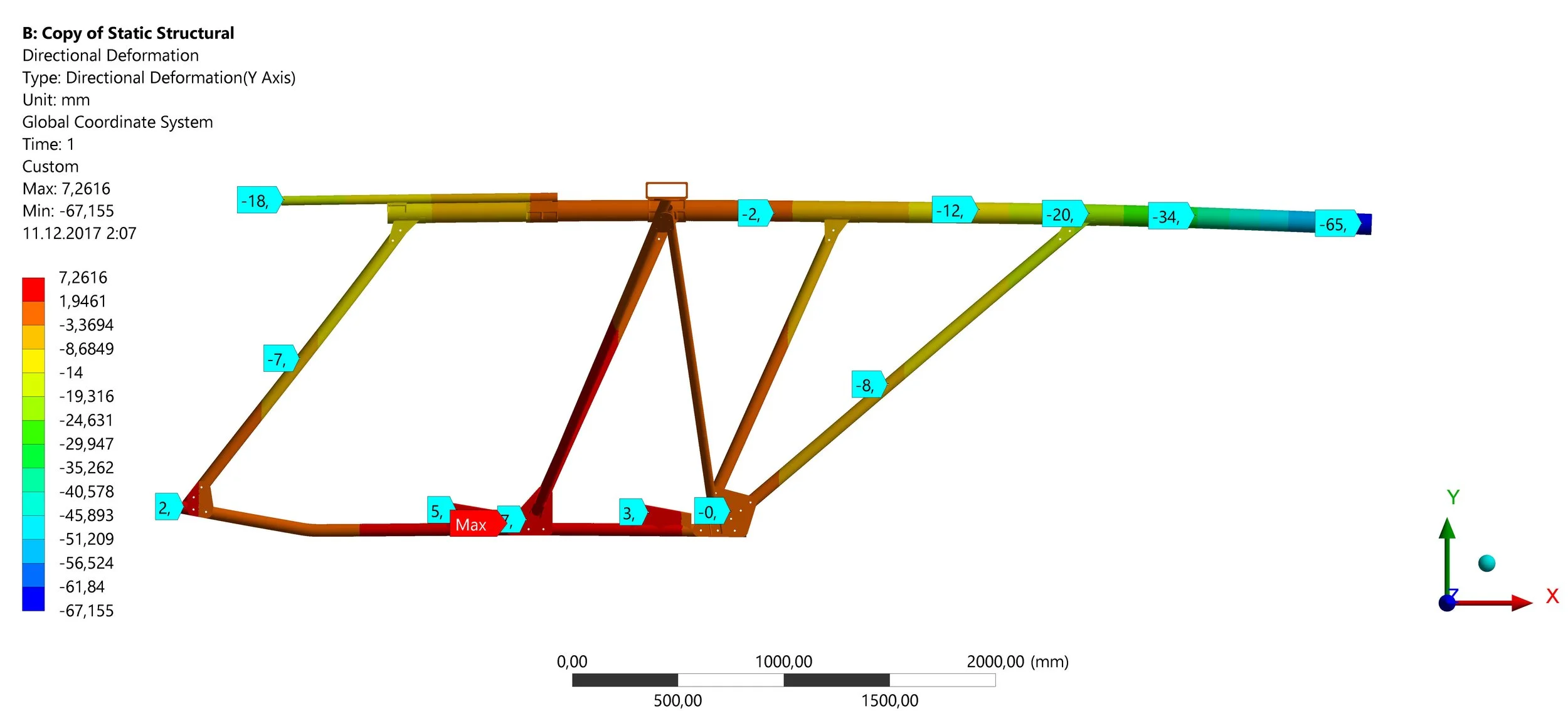
As shown in the picture above, most members operated under tension, but the tail brace support was massively compressed due to elevator forces. Even so, the FoS was above 1,7 on the back side of the tail member bracing support and above 2 for compressed rod buckling (shown in the following figure). Nevertheless, there are a couple of areas with FoS below 1. This tells us that there were no cases when the aeroplane achieved our specified limit load, and the chosen FoS was too high. Based on the lightness of the existing structure, it was decided to strengthen the highlighted zones but decrease the thickness of the top member and second pilot support member by 10%.
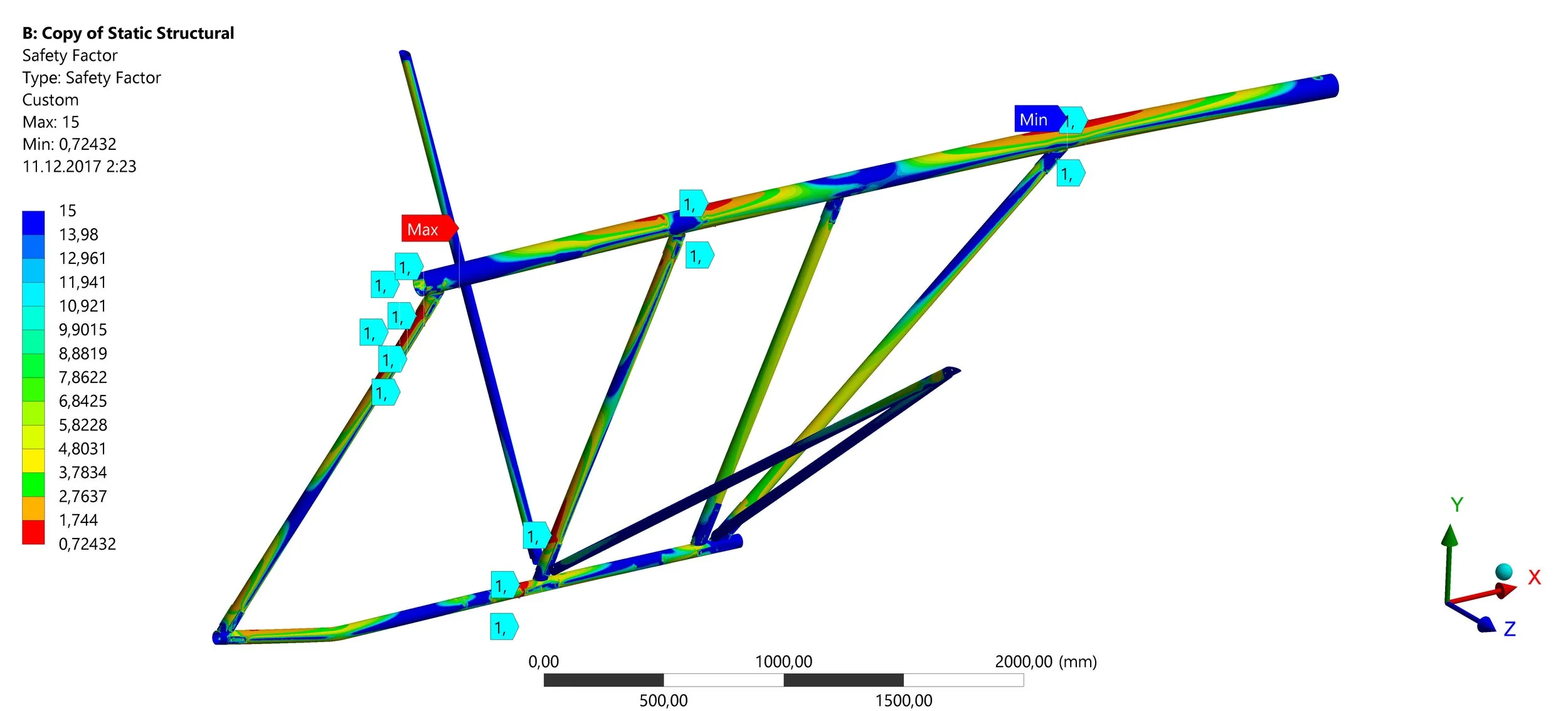
The analysis provided an understanding of the accelerations and loads acting on the airframe and showed problematic areas in the design. Using the analysis results, we created a weight-reduction plan (−8%) and increased the structural integrity of the joints with FoS that were below 1,3.
Understanding the compressing forces on the tail bracing support enabled us to design a tail member with a stressed shell mounted directly to the fuselage (see the following picture). As the result, the revised airplane was equipped with a glass fiber sandwich tail with increased stiffness (39mm of deformation instead of 65mm) and lower mass.
Key results