Development of the Formula SAE upright
Suspension, FSAE, CAD, FEA, Topology optimization, BS8888

In 2015 I was appointed as an NCM Polytech (FSAE) chief engineer. I was responsible for the development and testing of race cars. Because of the small number of mechanical engineers, I partially fulfilled the role of the suspension design lead. During two years in this role, I analysed tons of tire data, developed various CAD models and launched two formula cars. On this page, you will find the key stages of the formula car suspension upright development.
Project summary
• Suspension packaging
• CAD development
• Finite elements analysis (FEA)
• Drawings release
Responsibilities
1. Initial assembly development
2. FEA and topology optimization
3. Drawing development
Project objectives
A suspension upright is a vital element of the suspension assembly. The main functions of the upright are to withstand all the forces and moments occurring in the tire contact patch and transmit them to the chassis via suspension wishbones. At the same time, it is a core element of the wheel assembly that holds together the following components and systems:
• Outboard wishbone joints or brackets
• Tie rod or steering rod
• Wheel hub and bearings
• Brake rotor and calliper
• Cables and hydraulic lines fixings
• Sensors and auxiliary components
The biggest challenge in the FSAE upright development is the limited space, especially when the team run 10” wheel rims. The part must fit in the wheel and provide enough clearance and stiffness to prevent the brake calliper and wishbone brackets from scrubbing the rim under the load.
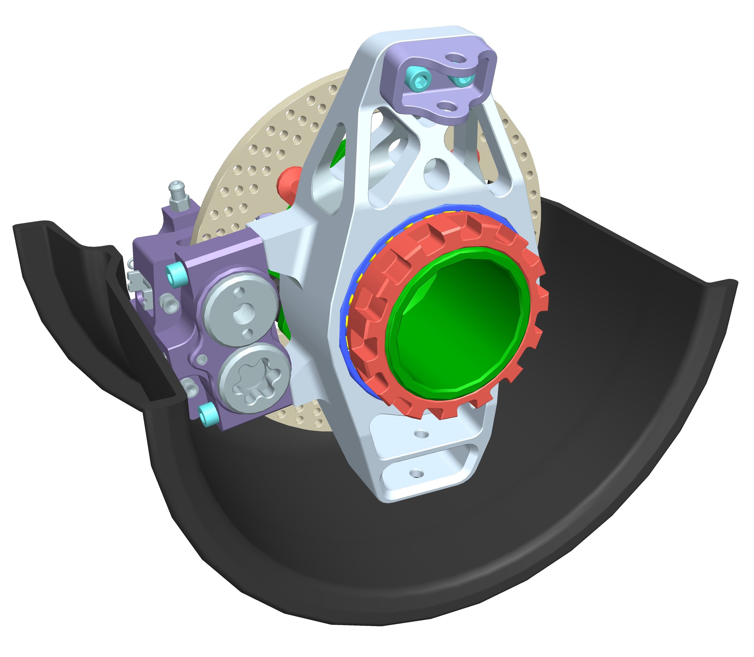
To begin the upright design, the team must freeze the suspension kinematics (pick-up points) and have at least the first iteration of the wheel packaging components (or validated geometry for off-the-shelve parts). In my team, the development of suspension kinematics was carried out using the MSC Adams Car. The geometry and the pick-up points were chosen according to the behaviour of the Pacejka 5.2 tire model, which was based on the TTC tire data. Considering this data, I began the initial assembly packaging using the Siemens NX software. As can be seen in the picture below, all the required components were placed and positioned inside the wheel rim. The components clearance was designed considering the wheel rim deformation under the heavy braking at the curb and the pure cornering load. However, the position of the brake calliper was chosen not only to provide the required braking torque but also, to optimize the "jacking" force (by lowering the wheel assembly CoG) and minimize the vehicle's yaw inertia.
1. Initial assembly development

The 10-inch wheels shown in the picture above present numerous challenges, necessitating a balance among suspension kinematics, brake caliper positioning, and brake rotor size.
Additionally, I have another project in my portfolio that posed even greater challenges for component packaging due to stringent aerodynamic requirements and limited frontal area: a solar-powered race car designed for the World Solar Challenge competition in Australia.
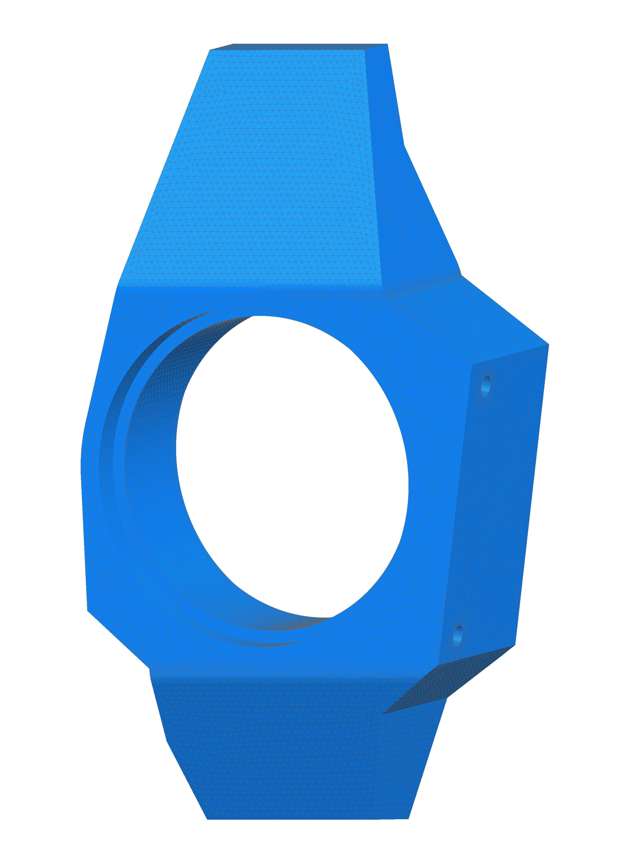
After releasing the position of the components, I created the simplified upright representation — "block". The "block" had bearing bores, a calliper mounting surface, and wishbone mount faces. The picture below shows the simplified initial geometry of the upright that will be fed to the topological optimization algorithm.
2. FEA and topology optimization

To provide the required strength and stiffness of the upright, the optimization was performed using the combination of the following critical cases:
• Outer wheel at apex
• Braking on the curb
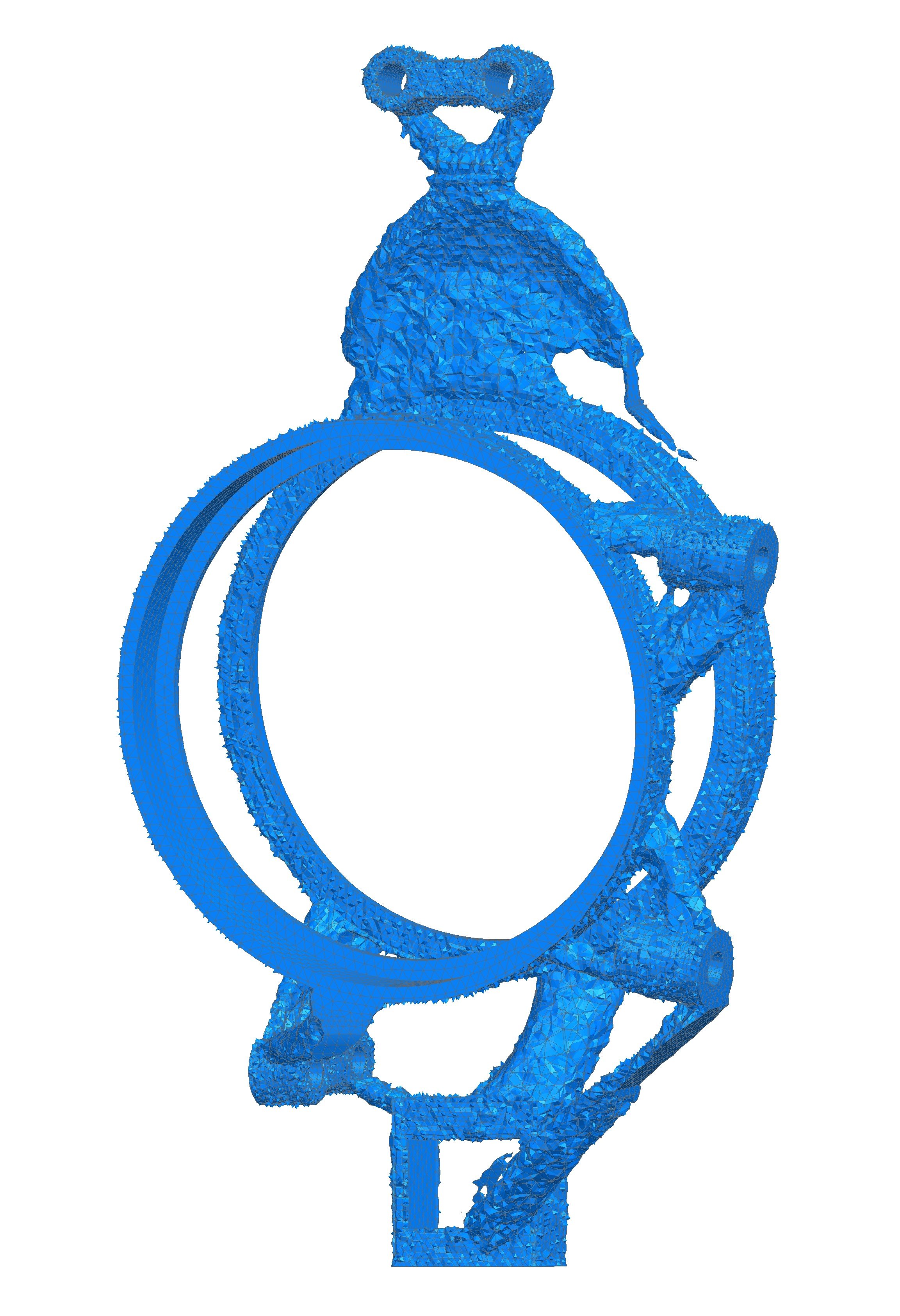
To conduct the optimization, I used the SOL 200 Nastran solution. The upright “block” was divided into “Frozen Features” that remain untouched and “Optimization Area” that was processed. Threads, fastener bosses and wishbones brackets played the “Frozen Features” role when the rest of the body was an optimization target.
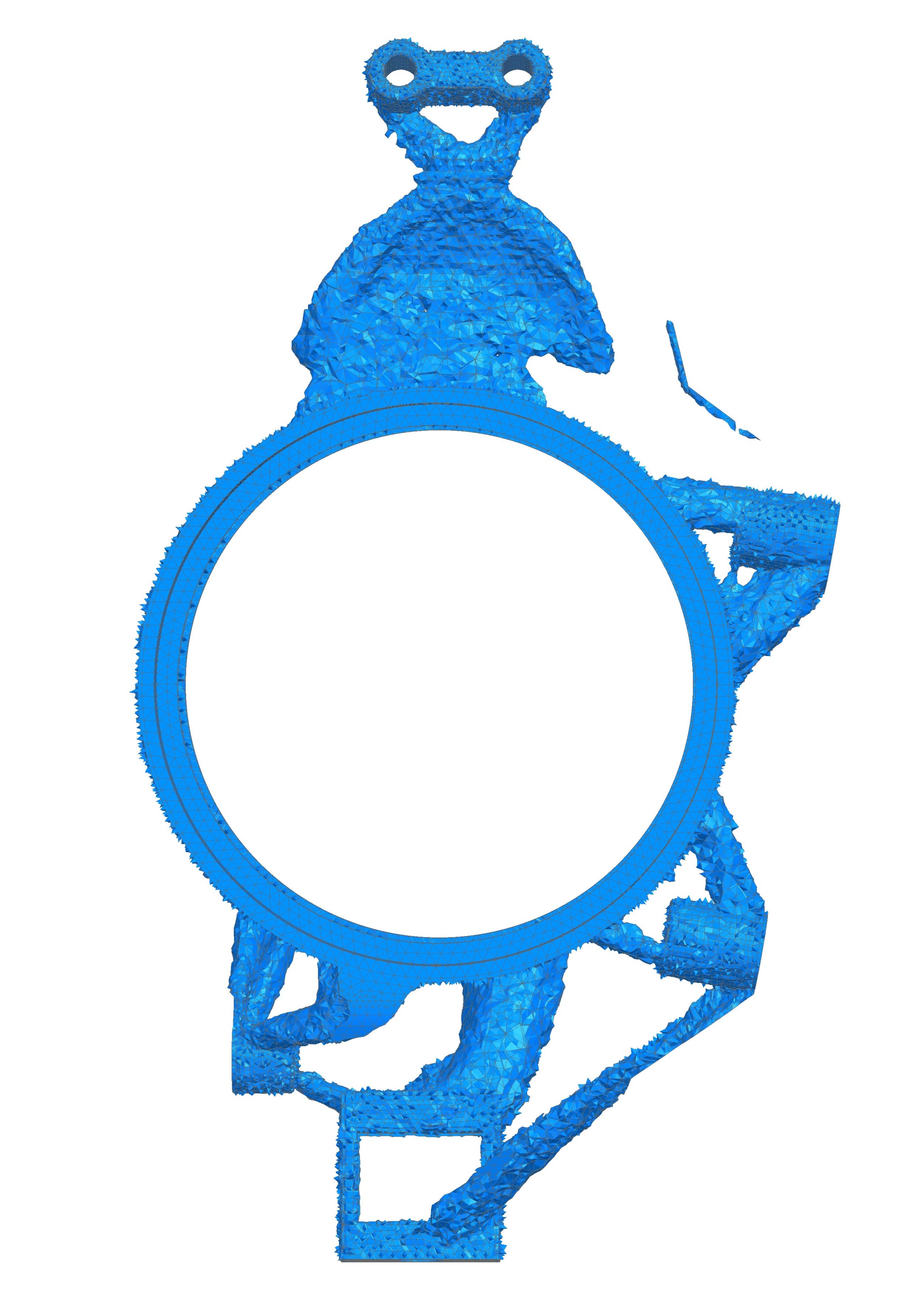
The main objective of the optimization was to minimize mass while keeping the stiffness within 90% of the initial geometry. During the optimization, I used the “Compliance” variable as the main input to control the overall stiffness and natural frequency of the upright. The raw optimized geometry is shown in the pictures below.
Due to a lack of access to the metal SLS technology, the freeform geometry was transformed into the geometry feasible for a 5-axis CNC milling machine. The adapted geometry was designed to provide a safety factor above 1,5 (for 7075-T6 alloy) and to be compatible with the two-stage manufacturing process (one flip of the part during the machining). To ensure manufacturability, the following auxiliary datum features were approved by the CNC operator:
• Frontal flat surface
• Rear flat surface
• Top horizontal surface
• Steering arm surface
However, according to the function of the upright, the centre bore of the outer bearing was used as a main datum feature (A) on the drawing. This was also convenient for the CNC machinist because most upright features were machined using the expansion clamp (by clamping the centre surface of the bore). The final upright geometry, including the features mentioned above and the released wheel assembly, are shown in the pictures below.
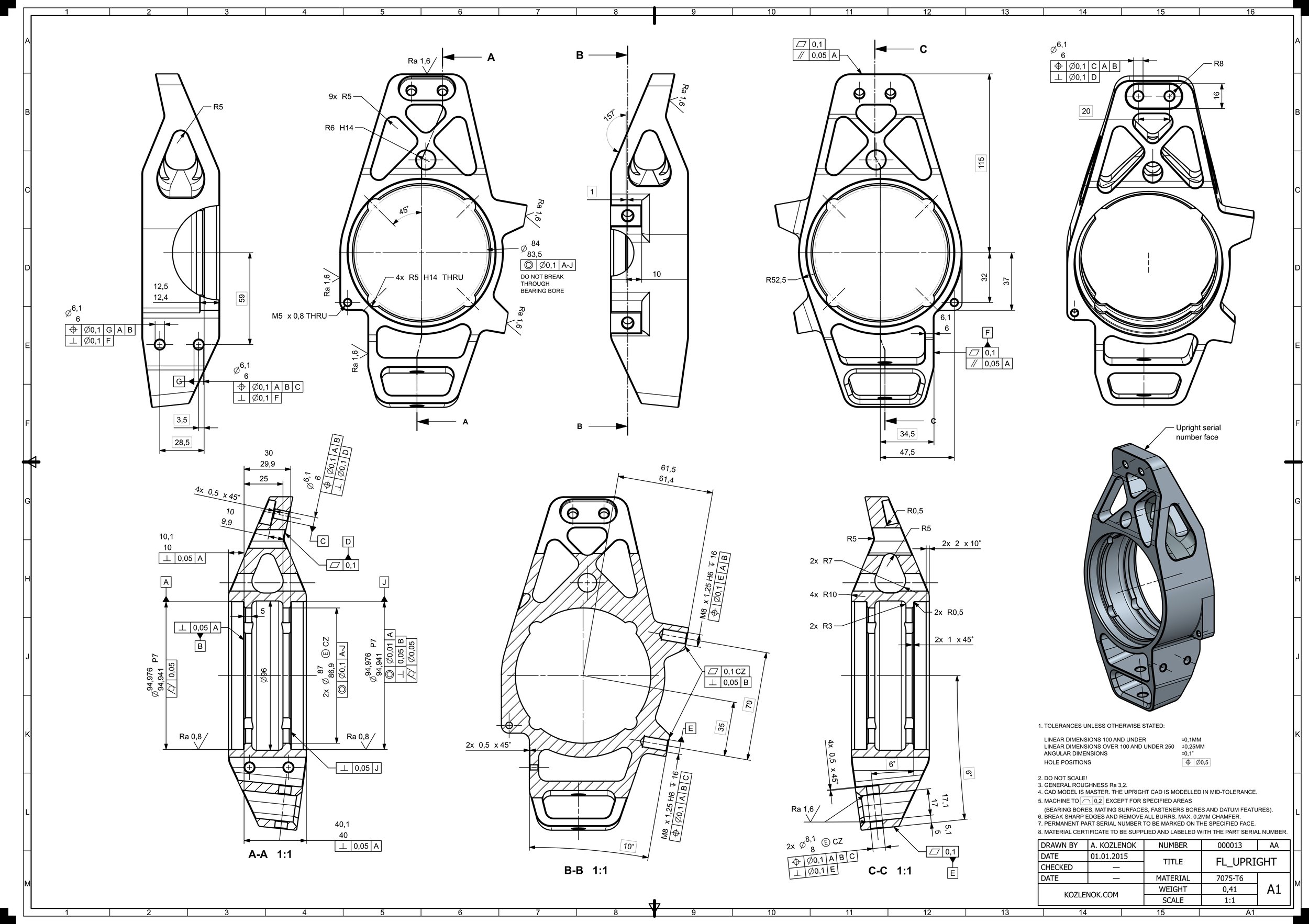
3. Drawing development

The main result of this project is the upright design that can provide the necessary stiffness to the system while simultaneously guaranteeing the pilot's safety and suspension reliability. The final geometry was created based on the results of topological optimization and recommendations from the CNC machine operator. Finally, the three-dimensional CAD geometry was supplemented with an advanced drawing to ensure high accuracy and minimize the chance of error. The final revision of the drawing was made according to BS8888 standard and is shown in the picture below.
Key results
Godspeed!