Development and Optimisation of an AMR Suspension
Suspension, AMR, Statistics, MatLab, Simulation
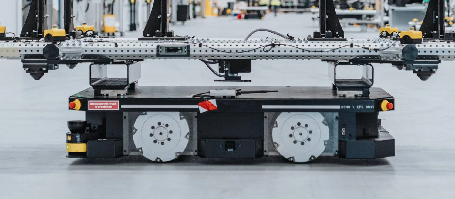
In 2021 I was responsible for the development of wheeled AMR chassis and components. Tests showed us that the quality of the factory floor is vital for the AMRs equipped with mecanum wheels. Local unevenness and variable coefficient of friction across the floor affected both positioning and movement accuracy. At the same time, the analysis showed us that the implementation of the suspension units could improve the AMR operation on the given floor.
UK-RAS mentioned this particular AMR as one of several technologies developed in the UK that provide numerous opportunities and strengths for advancing robotics interoperability.
Project summary
• CAD development
• Data processing and analysis
• Mathematical model development
• Prototype tests
Responsibilities
1. Creation of a simulation environment
2. Development and optimisation of the suspension
3. Evaluation of contact patches and joint forces and their distributions
Project objectives
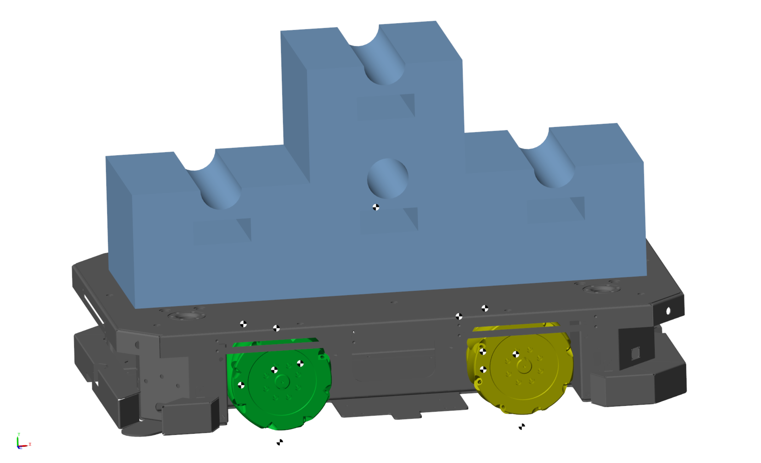
I chose the MatLab software package to optimise ROBOT kinematics and analyse suspension forces distribution. The robot model, its suspension, and a set of potential payloads were created in Simscape Multibody using existing CAD geometry and components inertia data. The mathematical model of the robot's motion was developed in Simulink, including the analysis of the forces acting at the joints and the contact patches. All cases were simulated with various payloads in different conditions (states).
Following simulation environment modes were created:
• Simulation using logs from an AMR data acquisition unit
• Virtual factory floor simulation
• Four-post rig shake simulation
1. Creation of a simulation environment
The project's initial phase involved researching existing standards for floor curvature and measuring the actual floor of the production site. Those measurements showed that the selected factory complied with the required FM2 classification (F and E parameters) defined by the Concrete Society's Technical Report Number 34. Based on the measured data, a floor model was built which controlled the robot's elevation parameter for each wheel. The variation of the height parameter was driven by an Interpolation function linked to the floor elevation map and the robot’s speed map in the simulation environment.
Using closed-loop optimisation, I arrived to a compromise between contact patch load variation; the required suspension frequencies; and the torsion of the chassis with the suspension. The variations were the lengths of the suspension elements within limits allowed by the robot geometry, as well as the stiffness and the positions of the spring.
2. Development and optimisation of the suspension

One of the most critical points of the development was the choice of the robot's suspension frequency. Because the robot was holonomic and did not have a defined direction of travel, the frequency of all suspension corners was chosen to be the same. Using a virtual four-post shake simulation, the suspension's natural frequency was shifted into a safe range according to the real AMR speed logs. All internal components, in particular, the element brackets were updated according to the results of the NX Response simulation. The robot control software also considered the unsuitable AMR speed range and planned the route to minimise the time spent in that range.
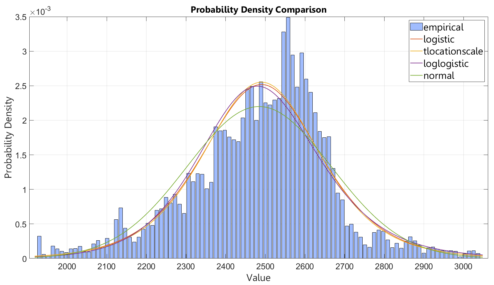
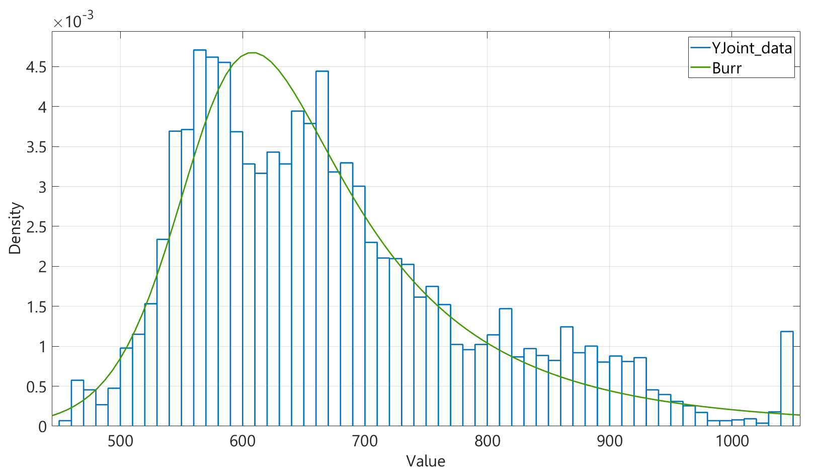
To determine the forces and torques acting on the joints, I created a scenario using the heaviest potential payload with the highest centre of gravity. The environment was equipped with a report generator to support further development of CAD, material selection, and FEA modelling. The statistical toolbox was used to determine the probability of the occurrence of the load values. The most appropriate distribution was chosen based on the MLE function because of the specificity of the data. Burr and Logistic distributions showed the most accurate fitting when the Variance value for both can be found as a sigma square (based on Chebyshev's inequality).
To improve components reliability, a strategy incorporating three safety factors was used:
• Abuse load condition (collision scenario)
• Limit load condition (μ+3*σ)
• Fatigue load condition (affecting the design according to the endurance limit)
3. Evaluation of contact patches and joint forces and their distributions
The most important result of the project was increased positioning accuracy of the wheeled AMR within the existing factory floor (FM2 floor class). A process was developed to use collected motion logs to generate a report with component loads. Such a report helped increase the robot components' reliability and established a stable factory operation. The created simulation environment not only helped reduce the number of physical tests and experiments to verify component reliability but also helped us to predict future robots' efficiency in the given conditions.
Key results