Logistics Robot Concept Development
Design, Concept, AGV, Casting, DFM, Manufacturing
In 2018 I finished developing the mechanical components of a two-wheeled logistics AGV for an automotive factory. After assembling several robots, we conducted acceptance tests to prove the concept. The tests revealed that launching this robot into production required a revision of several mechanical components and a harness redesign to simplify the assembly process and certification. The two-wheeled prototype had issues with production on the automated assembly line (not robotic friendly assembly sequence). Observing these test results and DFM analysis, I identified the most critical areas for a redesign and developed the new concept layout.
Project summary
• Product analysis
• Concept development
• AGV layout design
• CAD development
Responsibilities
1. Design definition (compatibility with DFM/DFA)
2. Assembly strategy development
Project objectives

The analysis of the existing prototype (GB2578903B) revealed that the majority of the elements and mechanisms could be re-used in the new prototype with minimal modifications to the plastic housings and minimal relocation of the fixing points. However, the welded steel frame had to be redesigned entirely due to its high manufacturing costs.
1. Design definition
The analysis of the Alpha version's assembly process revealed the following problems:
• Cables routing (the installation of controllers and sensors took up to 60% of assembly time)
• Elements and controllers had no mounts or specific positions because of double sided tape montage
• More than ten fastener types were used requiring many tools and frequent bit changes
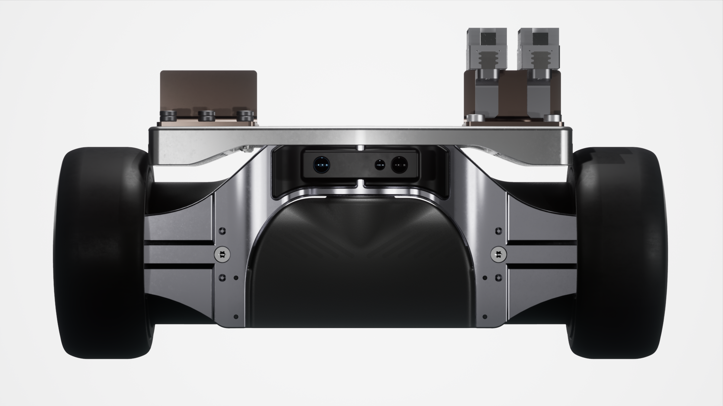
I decided to split the components into pre-assembled modules to solve wiring and harness problems. By creating electronic sub-assemblies I was able to replace the unreliable Micofit connectors with industrial-grade sealed connectors. The layout of the custom PCBs was revised to group the input and output connectors on one side. The power and signal wires of the motors and battery were combined using blade bay Molex EXTreme power connectors. This solution allowed for a direct mounting of the motors to the battery module.
The change from a welded tubular steel frame to a cast aluminium frame provided additional surfaces for mounting pads and mounting holes. The technology has made it possible to place bosses on mounting pads to control the position of components and reduce the number of fasteners. Because of the split chassis, some internal components were secured with pins instead of bolts, compensating for the access difficulty.
2. Assembly strategy development

Based on the mass production requirements, it was reasonable to switch to a casted machined alloy frame and re-design a number of plastic elements for injection moulding. It was decided to use investment casting technology because of several thin concave-shaped features; external surface quality, and small first batch quantity. Investment casting minimised the three-axis machining of the finished product, resulting in faster prototyping and testing. The A356 aluminium alloy was chosen for the casting because of its high accessibility, low cost, and suitability for prototype endurance limit (up to 85MPa). The part's geometry has been designed with the “thick to thin" principle, where the alloy is poured through the area with the thickest wall. Because of its geometry, the central joint of the frame operates as a secondary riser system to reduce flanges shrinkage. The use of surface modeling tools allowed for smooth sectional transitions throughout the part from the main node joint to the flanges. The thickest wall belongs to the central joint and is up to 15mm thick when the flanges are only 8mm thick.
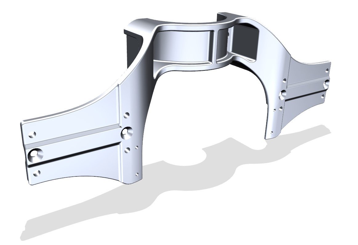
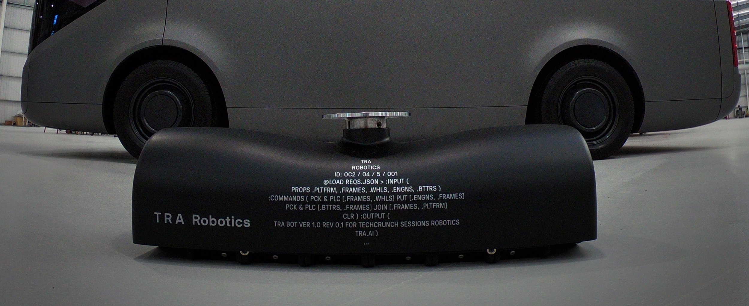
The proposed prototype was developed based on DFM/DFA principles to cut down the assembly time and ensure the perfect alignment of the components. The two-component subframe was cast and machined to ensure split surface quality and provide “robotic-friendly” clamping features.
Switching to the cast frame reduced stress in the structure and increased load capacity while providing a weight decrease. Because of the modular design of the new concept, the majority of components were re-used in their original form. At the same time, cables and harnesses were replaced with convenient EXTreme power connectors to provide a reliable signal and power lines connection. After revision, the entire AMR contained only four types of fasteners and was suitable for assembly by two KUKA KR6 robots in a 6m2 assembly cell.
The estimated assembly time was reduced by 150% compared to the original Alpha version.
Key results