Clutch Multibody Simulation - PhD Thesis Summary
Multibody Dynamics Simulation, MatLab, Friction Modelling, SLM, Additive Manufacturing
This page provides a comprehensive overview of my PhD research, which focuses on modifying the frictional freewheel clutch to to extend its operational speed range. My goal in this project was a pure self-challenge to improve my analytical skills and master data processing.
Project summary
Time allocation
| Activity | Tool | Hours |
|---|---|---|
| Research planning | Atlassian | 4 |
| Multibody simulation | MatLab Simulink | 110 |
| CAD | NX12 | 30 |
| CAE | Ansys Mechanical | 10 |
| Test stand assembly | Hands | 6 |
| Sensors calibration | 8-channel oscilloscope | 3 |
| Experiments | Custom test stand | 30 |
| Data analysis | MatLab Simulink | 50 |
| Graphs plotting | MatLab Simulink | 40 |
| Thesis - Initial writing | LaTex | 119.5 |
| Thesis - First editing | LaTex | 16.5 |
| Thesis - Second editing | LaTex | 7 |
| Thesis - Third editing | LaTex | 35 |
| Thesis - Fourth editing | LaTex | 19 |
| Documents submission | Legs | 15 |
| Total | — | 495 |
• Simulink SimScape Multibody;
• Control System Toolbox;
• Curve Fitting Toolbox;
• Optimization Toolbox;
• Symbolic Toolbox;
• Statistics Toolbox.
Used MATLAB packages
• Custom PMSM motor with Everest XCR 40/80 controller;
• ATI Omega 160 torque force sensor;
• 14 Bits Zettlex BSSI Incoders;
• TDK Lambda GEN 60–55 power supply;
• Shining 3D EP–M100T.
Used Equipment
1. Hypothesis
Freewheel wedge clutches are a commonly used type of clutch that can transmit high torque but have a limited speed range due to their design. Due to the high weight of active elements (compared with roller and cam clutches), this FWC type has high inertia. At the same time, the high contact area between elements leads to ineffective oil removal from the contact area, subsequently leading to a hydrodynamic lubrication regime. Both factors extend the engagement phase of the mechanism, which, at some speed, becomes equal to the whole cycle length and leads to complete slippage of the clutch.
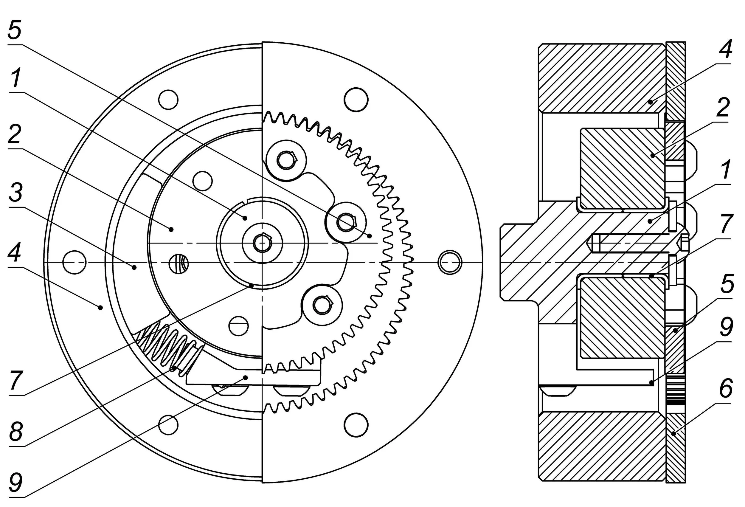
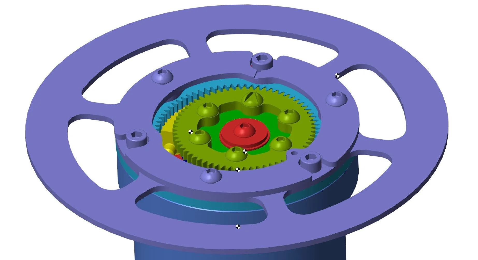
1. Input shaft (eccentric shape);
2. Eccentric’s roller;
3. Wedge;
4. Output shaft;
5. Eccentric’s roller pinion;
6. Output shaft internal gear;
7. Sliding bearings (other types can be used);
8. Preload spring;
9. Spring holder.
Surface channels or the porous body of the wedge could be a potential solution that decreases the thickness of the oil film and shifts the hydrodynamic lubrication to higher speeds, thereby improving the FWC's efficient range.
Such a solution can be manufactured using the state-of-the-art SLM technology. However, the strength and durability of the porous bodies in the FWC require validation and physical experiments.
2. Frictional clutch modelling
Literature research revealed that at the time of the study, there was no approach or model to simulate/calculate the detailed behavior of the FWC elements, visualize their behavior, or visualize the detailed distribution of forces acting on their elements.
To fully understand the operation of the wedged clutch, I created a multi-level mathematical model. The model consists of a “Multibody layer” to describe kinematics and simulate inertia using CAD models of the components, a “Frictional layer” to calculate all forces and moments acting on the elements, and an output computational block to calculate the output power and efficiency of the mechanism.

The “Multibody layer” consists of the joints and linked solid models of FWC components, which are represented by the inertia tensor and CAD geometry. The “Frictional layer” consists of 10 contacts (five on each side of the wedge). Each contact is simulated using elements of the Simscape Multibody Contact Forces Library.
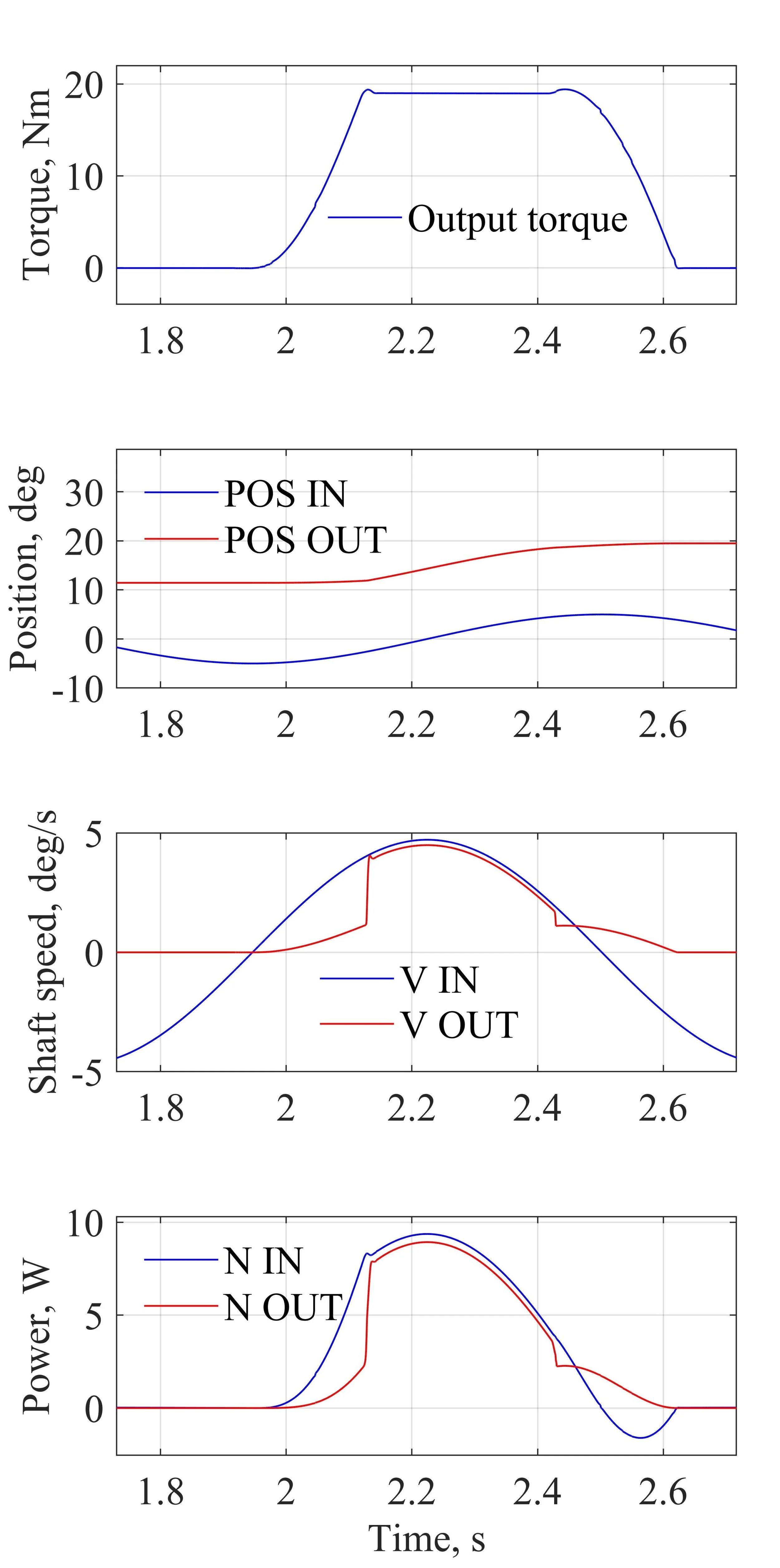
As the output of the simulation, the model creates a dashboard with eight plots:
1. Output torque;
2. Angular positions of the input and output shafts;
3. Shaft speeds;
4. Input and output power.
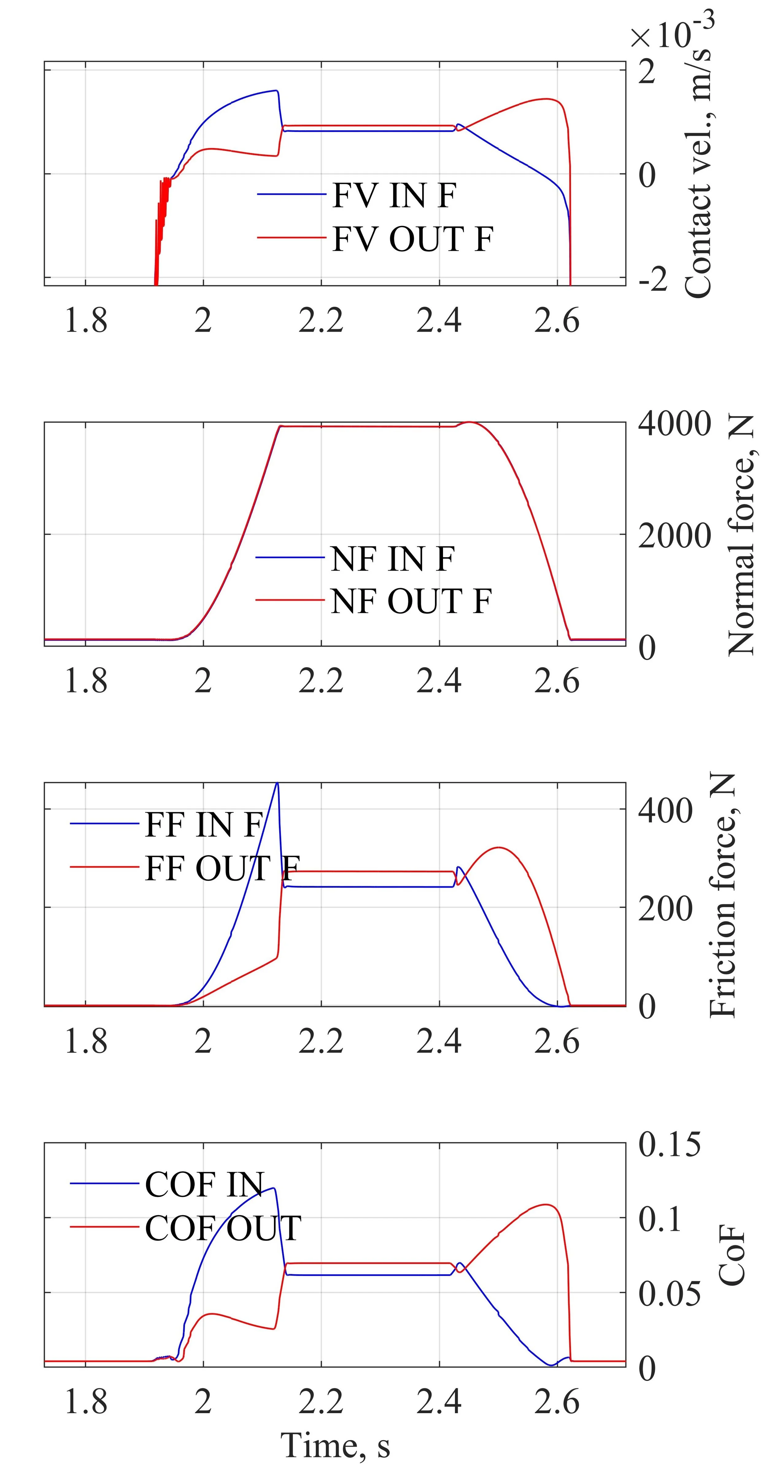
5. Velocity in the contact patch;
6. Normal force in contact patch;
7. Frictional force in the contact patch;
8. Coefficient of friction in specified contact.
Note: The mathematical model can’t accurately predict the Stribeck curve, but it can demonstrate how variations in the FWC parameters (including the CoF behavior on the wedge surfaces) affect the mechanism's efficiency.
3. Validation
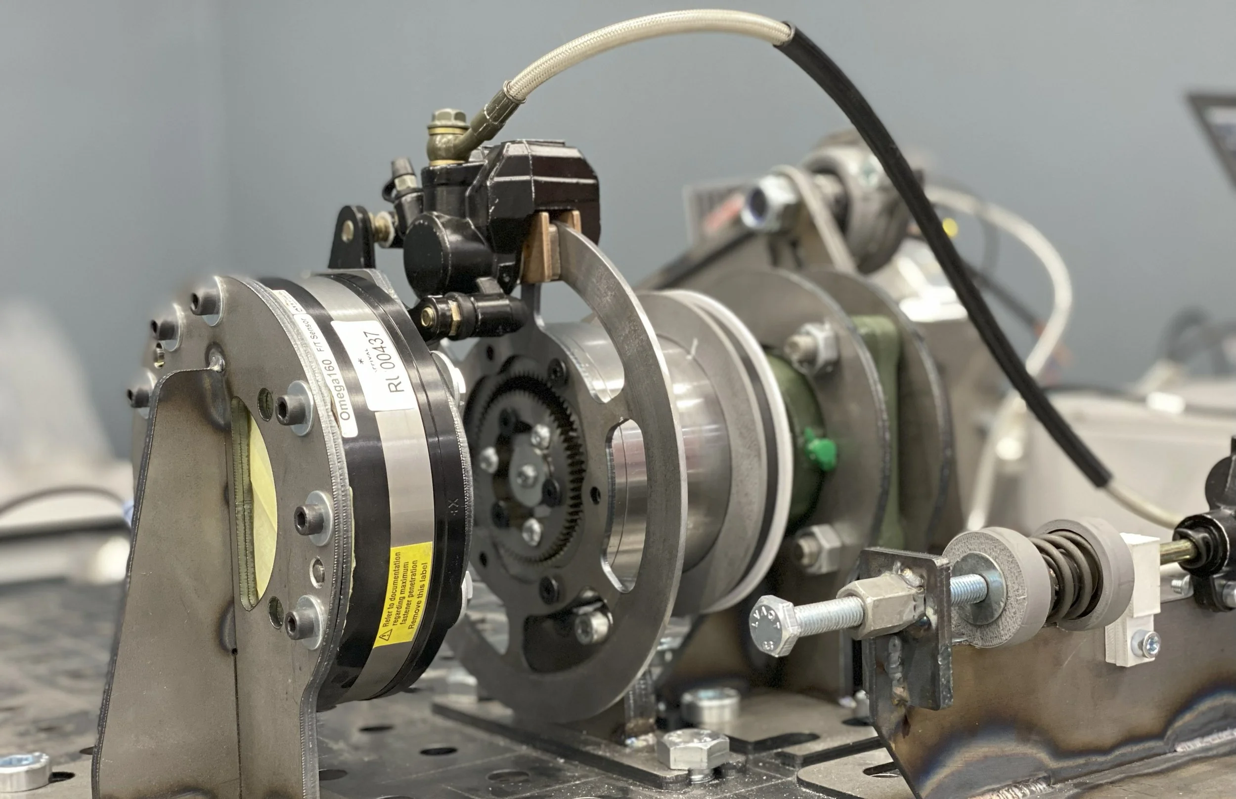
To validate the mathematical model and the hypothesis of the porous wedge, I developed the test stand with the FWC assembly and manufactured various wedge prototypes using SLM technology.
The test stand enables the installation of wedge prototypes and the running of experiments at various speeds across a wide range of torque loads. The sensor stack of the stand collects input and output shaft angular position and velocity, as well as the output torque of the FWC.
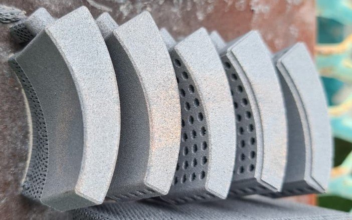
To validate the hypothesis of the improvement of the speed range of the FWC by using the controlled porosity of the wedge, I tested the following wedge prototypes:
• Solid wedge (A);
• Wedge with channels and porosity on both sides (B);
• Wedge with porosity on the side that contacts the output element of the FWC (C).

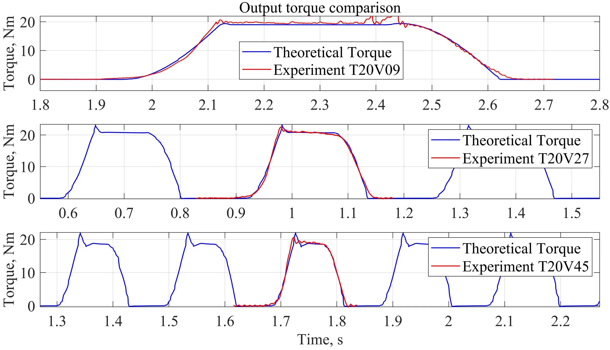
4. Data analysis
To validate the hypothesis, I conducted 75 experiments with the three wedges mentioned above. Each wedge was tested at five different speeds and five different load steps at each speed. The assumption was that the wedge with the least correlation to the shaft speed increment would have the widest speed range.
The processed data confirmed the hypothesis, revealing that the efficiency of the wedge with modifications on both sides does not correlate with FWC speed. At the same time, the FWC equipped with a modified wedge can operate at higher speeds.
The scatter plot below shows that the FWC equipped with the wedge “B” barely depends on the speed of the input shaft (at least within the specified range) and can operate at higher speeds compared with the FWC equipped with the two other samples.

As you can see on the plot, both wedges “B“ and “C“ have at least 4 degrees of the FWC output shaft rotation per cycle, while wedge “A“ (without modifications) had an output shaft rotation per cycle below 1 degree at input frequencies above 3 Hz (see red dots in the top left corner of the top plot).
Besides that, you can see that wedge “A“ has a strong correlation (R=-0.91) between the input frequency and output shaft rotation per cycle (the more the input frequency, the less rotation of the output shaft due to hydrodynamic lubrication regime). At the same time, wedges “B“ and “C“ have almost no correlation between these parameters (R=-0.1 and R=-0.27) because of the effective oil drainage through the porous surfaces.
5. Conclusion
The research revealed that state-of-the-art SLM printing technology can deliver high-integrity porous components, thereby improving the characteristics of well-known mechanisms. The data analysis confirmed that modifying the wedge's working surfaces can improve the wedged FWC's efficiency by decreasing the engagement phase due to enhanced oil drainage from the contact area.
Besides that, the endurance tests of the modified component confirmed that the wear of the modified surfaces does not affect the efficiency of the FWC due to the nature of the porous segments and channels that run throughout the wedge body (wear of the surface opens new porous enclosures and creates new pathways for the oil).
References
Aleksandr Kozlenok. An approach for the simulation of the wedge freewheel clutch as a frictional multibody dynamic system. Tribology International, Volume 193, 2024.
Steve Miller (2025). Simscape Multibody Contact Forces Library; (https://github.com/mathworks/Simscape-Multibody-Contact-Forces-Library/releases/tag/24.2.5.2), GitHub. Abgerufen9. August 2025.
Wall of fame
This could not be possible without the following people:
Arina Baranova - Patience and visual guidance of the thesis and plots;
Dr. Igor Petranevsky - Day and night support with multibody simulation and mathematical modeling;
Leo Lesin - For research guidance and help with sensor implementation;
Sergey Kalenykh - Prototyping, test stand assembly, and help with experiments;
Ivan Girsov - Helped conduct hundreds of experiments during the research;
Vladislav Ivanov - Helped to collect and organize 150+ pages of documents;
Aleksandr Rybnikov - Multiple advices and onboarding on the data processing;
Danil Petrov - Guidance with data processing and troubleshooting during mathematical modeling;
Tikhon Uglov - Helped to find the answers to the most complex questions;
Dr. Ass. Prof. Ivan Selin - For the guidance with documentation and a nice title;
Dr. Prof. Roman Dobretsov - Four years of motivation and multiple thesis reviews;
Dr. Andrey Urkevich - Help with documents and numerous reviews;
Dr. Giuseppe Napo Montano - Mentorship and motivation (There is a light at the end of this tunnel);
Dr. Bingyin Ma - Support and motivation.
Thank you all!